


The Capacitor or sometimes referred to as a Condenser is a passive device, one which stores energy in the form of an electrostatic field which produces a potential (Static Voltage) across its plates.
In its basic form a capacitor consists of two parallel conductive plates that are not connected but are electrically separated either by air or by an insulating material called the Dielectric.
When a voltage is applied to these plates, a current flows charging up the plates with electrons giving
one plate a positive charge and the other plate an equal and opposite negative charge. This flow of electrons to the plates is known as the Charging Current and continues to flow until the voltage across the plates (and hence the capacitor) is equal to the applied voltage Vc. At this point the capacitor is said to be fully charged and this is illustrated below.
one plate a positive charge and the other plate an equal and opposite negative charge. This flow of electrons to the plates is known as the Charging Current and continues to flow until the voltage across the plates (and hence the capacitor) is equal to the applied voltage Vc. At this point the capacitor is said to be fully charged and this is illustrated below.
CAPACITOR CONSTRUCTION

The parallel plate capacitor is the simplest form of capacitor and its capacitance value is fixed by the equal area of the plates and the distance or separation between them. Altering any two of these values alters the the value of its capacitance and this forms the basis of operation of the variable capacitors. Also, because capacitors store the energy of the electrons in the form of an electrical charge on the plates the larger the plates and/or smaller their separation the greater will be the charge that the capacitor holds for any given voltage across its plates.
By applying a voltage to a capacitor and measuring the charge on the plates, the ratio of the charge Q to the voltage V will give the capacitance value of the capacitor and is therefore given as
C = Q/V
This equation can also be re-arranged to give the more familiar formula for the quantity of charge on the plates as
Q = C x V
UNIT OF CAPACITANCE:
The unit of capacitance is the Farad (abbreviated to F)
A capacitor has the capacitance of One Farad when a charge of One Coulomb is stored on the plates by a voltage of One volt. Capacitance, C is always positive and has no negative units. However, the Farad is very large units of measurement to use on its own so sub-multiples of the Farad are generally used such as micro-farads, nano-farads and pico-farads, for example.
- Microfarad (μF) 1μF = 1/1,000,000 = 0.000001 = 10-6 F
- Nanofarad (nF) 1nF = 1/1,000,000,000 = 0.000000001 = 10-9 F
- Picofarad (pF) 1pF = 1/1,000,000,000,000 = 0.000000000001 = 10-12 F
BREAKDOWN VOLTAGE
When using a capacitor, you must pay attention to the maximum voltage which can be used. This is the "breakdown voltage." The breakdown voltage depends on the kind of capacitor being used. You must be especially careful with electrolytic capacitors because the breakdown voltage is comparatively low. The breakdown voltage of electrolytic capacitors is displayed as Working Voltage.
The breakdown voltage is the voltage that when exceeded will cause the dielectric (insulator) inside the capacitor to break down and conduct. When this happens, the failure can be catastrophic.
The breakdown voltage is the voltage that when exceeded will cause the dielectric (insulator) inside the capacitor to break down and conduct. When this happens, the failure can be catastrophic.
CAPACITOR COLOUR CODES:
Generally, the values of Capacitance, Voltage or Tolerance are marked onto the body of the capacitors. However, when the value of the capacitance is of a decimal value problems arise with the marking of a "Decimal Point" as it could easily no be noticed resulting in a misreading of the actual value. Instead letters such as p (pico) or n (nano) are used in place of the decimal point to identify its position. For example, a capacitor can be labelled as, n47 = 0.47nF, 4n7 = 4.7nF or 47n = 47nF.
To reduce the confusion regarding letter, numbers and decimal points, an International colour coding scheme was developed many years ago as a simple way of identifying capacitor values and tolerances. It consists of coloured bands (in spectral order) whose meanings are illustrated below:

Like resistors, small capacitors such as film or disk types where the colours are replaced by a letter or number coded system. The code consists of 2 or 3 numbers and an optional tolerance letter code. Where a two number code is used the value of the capacitor only is given in picofarads (ie. 47 = 47 pF). A three letter code consists of the two value digits and a multiplier much like a resistor colour code (ie. 471 = 47*10 = 470pF). Three digit codes are often accompanied by an additional tolerance letter code as given below.
CAPACITOR TOLERANCE LETTER CODES TABLE
Letter
|
B
|
C
|
D
|
F
|
G
|
J
|
K
|
M
|
Z
| |
Tolerance
|
C <10pF ±pF
|
0.1
|
0.25
|
0.5
|
1
|
2
| ||||
C >10pF ±%
|
0.5
|
1
|
2
|
5
|
10
|
20
|
+80-20
|
Then just by using number and Letter codes on the body of the capacitor we can easily determine the value of its capacitance either in Picofarad's, NanoFarads or Microfarads and these codes are given in the following table along with the equivalent capacitances
CAPACITOR LETTER CODES TABLE
Picofarad
(pF) |
Nanofarad
(nF) |
Microfarad
(uF) |
Code
|
Picofarad
(pF) |
Nanofarad
(nF) |
Microfarad
(uF) |
Code
|
10
|
0.01
|
0.00001
|
100
|
4700
|
4.7
|
0.0047
|
472
|
15
|
0.015
|
0.000015
|
150
|
5000
|
5.0
|
0.005
|
502
|
22
|
0.022
|
0.000022
|
220
|
5600
|
5.6
|
0.0056
|
562
|
33
|
0.033
|
0.000033
|
330
|
6800
|
6.8
|
0.0068
|
682
|
47
|
0.047
|
0.000047
|
470
|
10000
|
10
|
0.01
|
103
|
100
|
0.1
|
0.0001
|
101
|
15000
|
15
|
0.015
|
153
|
120
|
0.12
|
0.00012
|
121
|
22000
|
22
|
0.022
|
223
|
130
|
0.13
|
0.00013
|
131
|
33000
|
33
|
0.033
|
333
|
150
|
0.15
|
0.00015
|
151
|
47000
|
47
|
0.047
|
473
|
180
|
0.18
|
0.00018
|
181
|
68000
|
68
|
0.068
|
683
|
220
|
0.22
|
0.00022
|
221
|
100000
|
100
|
0.1
|
104
|
330
|
0.33
|
0.00033
|
331
|
150000
|
150
|
0.15
|
154
|
470
|
0.47
|
0.00047
|
471
|
200000
|
200
|
0.2
|
254
|
560
|
0.56
|
0.00056
|
561
|
220000
|
220
|
0.22
|
224
|
680
|
0.68
|
0.00068
|
681
|
330000
|
330
|
0.33
|
334
|
750
|
0.75
|
0.00075
|
751
|
470000
|
470
|
0.47
|
474
|
820
|
0.82
|
0.00082
|
821
|
680000
|
680
|
0.68
|
684
|
1000
|
1.0
|
0.001
|
102
|
1000000
|
1000
|
1.0
|
105
|
1500
|
1.5
|
0.0015
|
152
|
1500000
|
1500
|
1.5
|
155
|
2000
|
2.0
|
0.002
|
202
|
2000000
|
2000
|
2.0
|
205
|
2200
|
2.2
|
0.0022
|
222
|
2200000
|
2200
|
2.2
|
225
|
3300
|
3.3
|
0.0033
|
332
|
3300000
|
3300
|
3.3
|
335
|
TYPES OF CAPACITOR:
There are many types of capacitor but they can be split into two groups,
· Polarised
· Non – polarized
1. DIELECTRIC
Dielectric Capacitors are usually of the variable type such as used for tuning transmitters, receivers and transistor radios. They have a set of fixed plates and a set of moving plates that mesh with the fixed plates and the position of the moving plates with respect to the fixed plates determines the overall capacitance. The capacitance is generally at maximum when the plates are fully meshed. High voltage type tuning capacitors have relatively large spacings or air-gaps between the plates with breakdown voltages reaching many thousands of volts.
Variable Capacitor Symbols

As well as the continuously variable types, preset types are also available called Trimmers. These are generally small devices that can be adjusted or "pre-set" to a particular capacitance with the aid of a screwdriver and are available in very small capacitances of 100pF or less and are non-polarized.
2. FILM CAPACITORS
Film Capacitors are the most commonly available of all types of capacitors, consisting of a relatively large family of capacitors with the difference being in their dielectric properties. These include polyester (Mylar), polystyrene, polypropylene, polycarbonate, metallized paper, teflon etc. Film type capacitors are available in capacitance ranges from 5pF to 100uF depending upon the actual type of capacitor and its voltage rating. Film capacitors also come in an assortment of shapes and case styles which include:
- Wrap & Fill (Oval & Round) - where the capacitor is wrapped in a tight plastic tape and have the ends filled with epoxy to seal them.
- Epoxy Case (Rectangular & Round) - where the capacitor is encased in a moulded plastic shell which is then filled with epoxy.
- Metal Hermetically Sealed (Rectangular & Round) - where the capacitor is encased in a metal tube or can and again sealed with epoxy.
All the above case styles are available in both Axial and Radial Leads.
Examples of film capacitors are the rectangular metallized film and cylindrical film & foil types as shown below.

The film and foil types of capacitors are made from long thin strips of thin metal foil with the dielectric material sandwiched together which are wound into a tight roll and then sealed in paper or metal tubes. This film type require a much thicker dielectric film to reduce the risk of tears or punctures in the film, and is therefore more suited to lower capacitance values and larger case sizes.
Metallized foil capacitors have the conductive film metallized sprayed directly onto each side of the dielectric which gives the capacitor self-healing properties and can therefore use much thinner dielectric films. This allows for higher capacitance values and smaller case sizes for a given capacitance. Film and foil capacitors are generally used for higher power and more precise applications.
3. CERAMIC CAPACITORS
Ceramic Capacitors or Disc Capacitors as they are generally called are made by coating two sides of a small porcelain or ceramic disc with silver and are then stacked together to make a capacitor. For very low capacitance values a single ceramic disc of about 3-6mm is used. Ceramic capacitors have a high dielectric constant (High-K) and are available so that relatively high capacitances can be obtained in a small physical size. They exhibit large non-linear changes in capacitance against temperature and as a result are used as de-coupling or by-pass capacitors as they are also non-polarized devices. Ceramic capacitors have values ranging from a few picofarads to one or two microfarads but their voltage ratings are generally quite low.
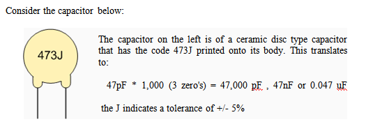
Ceramic types of capacitors generally have a 3-digit code printed onto their body to identify their capacitance value. For example, 103 would indicate 10 x 103pF which is equivalent to 10,000 pF or 0.01μF. Likewise, 104 would indicate 10 x 104pF which is equivalent to 100,000 pF or 0.1μF and so on. Letter codes are sometimes used to indicate their tolerance value such as: J = 5%, K = 10% or M = 20% etc.
4. ELECTROLYTIC CAPACITORS
Electrolytic Capacitors are generally used when very large capacitance values are required. Here instead of using a very thin metallic film layer for one of the electrodes, a semi-liquid electrolyte solution in the form of a jelly or paste is used which serves as the second electrode (usually the cathode). The dielectric is a very thin layer of oxide which is grown electro-chemically in production with the thickness of the film being less than ten microns. This insulating layer is so thin that it is possible to make large value capacitors of a small size. The majority of electrolytic types of capacitors are Polarized, that is the voltage applied to the capacitor terminals must be of the correct polarity as an incorrect polarization will break down the insulating oxide layer and permanent damage may result.
Electrolytic Capacitors are generally used in DC power supply circuits to help reduce the ripple voltage or for coupling and decoupling applications. Electrolytic's generally come in two basic forms; Aluminum Electrolytic and Tantalum Electrolytic capacitors.

1. ALUMINIUM ELECTROLYTIC CAPACITORS
There are basically two types of Aluminium Electrolytic Capacitor, the plain foil type and the etched foil type. The thickness of the aluminium oxide film and high breakdown voltage give these capacitors very high capacitance values for their size. The etched foil type differs from the plain foil type in that the aluminium oxide on the anode and cathode foils has been chemically etched to increase its surface area and permittivity. This gives a smaller sized capacitor than a plain foil type of equivalent value but has the disadvantage of not being able to withstand high AC currents compared to the plain type. Also their tolerance range is quite large up to 20%. Etched foil electrolytic's are best used in coupling, DC blocking and by-pass circuits while plain foil types are better suited as smoothing capacitors in power supplies. Typical values of capacitance range from 1uF to 47000uF. Aluminium Electrolytic's are "polarized" devices so reversing the applied voltage on the leads will cause the insulating layer within the capacitor to be destroyed along with the capacitor, "so be aware".
2. TANTALUM ELECTROLYTIC CAPACITORS
Tantalum Electrolytic Capacitors or Tantalum Beads, are available in both wet (foil) and dry (solid) electrolytic types with the dry or solid tantalum being the most common. Solid tantalums use manganese dioxide as their second terminal and are physically smaller than the equivalent aluminium capacitors. The dielectric properties of tantalum oxide is also much better than those of aluminium oxide giving a lower leakage currents and better capacitance stability which makes them suitable for timing applications. Also tantalum capacitors although polarized, can tolerate being connected to a reverse voltage much more easily than the Aluminium types but are rated at much lower working voltages. Typical values of capacitance range from 47nF to 470uF.
Aluminium & Tantalum Electrolytic Capacitor

CAPACITOR CHARACTERISTICS
There are bewildering arrays of characteristics associated with the humble capacitor so here are just a few of the more important ones.
1. Working Voltage, (Vn)
The Working Voltage (Wvdc, Wvac) is the maximum continuous voltage that can be applied to the capacitor without failure during its working life. DC and AC values are usually not the same as the AC value refers to the r.m.s. value. Common working DC voltages are 10V, 16V, 25V, 35V, 63V, 100V, 160V, 250V, 400V and 1000V and are printed onto the body of the capacitor.
2. Tolerance, (±%)
As with resistors, Capacitors also have a tolerance rating expressed as a plus-or-minus value either in Picofarads (±pF) for low value capacitors generally less than 10pF or as a percentage (±%) for higher value capacitors generally higher than 10pF. Capacitors are rated according to how near their actual values are to the rated capacitance with coloured bands or letters used to indicated the actual tolerance. The most common tolerance for capacitors is 5% or 10% but some electrolytic capacitors are rated as high as 20%.
3. Leakage Current
The dielectric used inside the capacitor is not a perfect insulator resulting in a very small current flowing or "leaking" through the dielectric when applied to a constant supply voltage. This small current flow in the region of micro amps (μA) is called the Leakage Current. This leakage current is a result of electrons physically making their way through the dielectric medium, around its edges or across the leads. The "leakage current" of a capacitor is sometimes called the "insulation resistance" and can be found using Ohm's law. The film/foil type capacitor has extremely low leakage currents while the leakage current of aluminium electrolytic's increases with temperature.
4. Working Temperature, (T)
Changes in temperature around the capacitor affect the value of the capacitance because of changes in the dielectric. If the air or surrounding temperature becomes to hot or to cold the capacitance value of the capacitor may change so much as to affect the correct operation of the circuit. The normal working range for most capacitors is -30°C to +125°C with nominal voltage ratings given for a working temperature of no more than +70°C. Generally electrolytic's can not be used below about -10°C, as the electrolyte jelly freezes.
5. Temperature Coefficient, (TC)
The Temperature Coefficient of a capacitor is the change in its capacitance with temperature expressed linearly as parts per million per degree centigrade (PPM/°C), or as a percent change over a specified temperature range. Some capacitors are non linear and increase their value as the temperature rises giving a temperature coefficient that is expressed as a positive (p.t.c.). Some capacitors decrease their value as the temperature rises giving a temperature coefficient that is expressed as a negative (n.t.c.). For example ±10%, or +80% / -20% etc. However, some capacitors do not change their value and remain constant over a certain temperature range, such capacitors have a zero temperature coefficient.
It is also possible to connect a capacitor with a positive temperature coefficient in series or parallel with a capacitor having a negative temperature coefficient the net result being that the two opposite effects will cancel each other out over a certain range of temperatures. Another useful application of temperature coefficient capacitors is to use them to cancel out the effect of temperature on other components within a circuit, such as inductors or resistors etc.
6. Polarization
Polarization generally refers to the Electrolytic type capacitors but mainly the Aluminium Electrolytic's, with regards to their connection. The majority are polarized types, that is the voltage connected to the capacitor terminals must have the correct polarity, i.e. +ve to +ve and -ve to -ve. Incorrect polarization can cause the oxide layer inside the capacitor to break down resulting in very large currents flowing through the device. The majority of electrolytic capacitors have their -ve terminal clearly marked with a black stripe or black arrows down the side to prevent any incorrect connection. Some electrolytic's have their metal can connected to the negative terminal but high voltage types have their can insulated with the electrodes being brought out to separate spade or screw terminals for safety. Also, when using electrolytic's in power supply smoothing circuits care should be taken to prevent the sum of the peak DC value and AC ripple voltage from becoming a reverse voltage.
7. Equivalent Series Resistance, (ESR)
The Equivalent Series Resistance is the AC impedance of the capacitor when used at high frequencies and includes the resistance of the dielectric, plate and terminal leads. ESR acts like a resistor (less than 0.1Ω) in series with the capacitor (hence the name Equivalent Series Resistance), and is frequency dependant. The ESR of electrolytic capacitors increase over time as their electrolyte dries out. Capacitors with very low ESR ratings are available.