


Showing posts with label Resistor. Show all posts
Showing posts with label Resistor. Show all posts
Methods of Making Resistors
There are two main methods that are used to make resistors.
• The most common is to just have a bunch of wire wound up inside that little cylinder.
• Known as wire-wound resistors, they depend on the fact that a certain length of a
certain piece of wire will have a certain resistance.
• These resistors tend to be very reliable (with low tolerances), but cost more because of
the price of metals used in them and the machinery needed to carefully cut and wind the
wire.
• The other type of resistor is made of a piece of
carbon.
• Known as a composition resistor, they
depend on the size of the piece of carbon,
and the fact that carbon is a metalloid (has
some metal-like properties) that does
conduct electricity.
• Because they are made from cheap
carbon, composition resistors can cost
much less than similar wire-wound
resistors. The drawback is that the carbon
can be cracked while making them, or become cracked in use. They have higher
tolerances because of the uncertainty in cutting the carbon.
In some cases it is necessary to have a circuit with resistors that you can adjust.
• These resistors are known as potentiometers or variable resistors.
• Often they are just a modified version of a wire-wound resistor, although newer
versions use advanced electronics instead.
• You’ve used one if you’ve ever used a dimmer switch for lights in a room, or played with an
electric race car set.
• Most variable resistors are designed so that by turning a dial or sliding a switch, you change the
amount of conducting material the current has to go through.
• The more conducting material the current has to go through, the higher the resistance…
less material and the resistance is less.
Actual Resistors
The resistors that you would most likely see if you opened up a CD player,
VCR, or other electronic device would look like the ones in Figure 2.
• They basically look like little cylinders with colored lines painted on

• The colored lines tell you the resistance and error range (tolerance) for
a resistor according to the following rules and table of numbers. You
do NOT have to memorize this table… it will be given to you if you
need it.
• To use the table you need to remember the following rules:
1. The first line is the first digit
2. The second line is the second digit
3. The third line is the multiplier
4. The last line (if any) is the tolerance
• Some resistors may have additional colored bands, but we will ignore them here.
• They usually have something to do with measuring things like failure rates or
temperature coefficients.
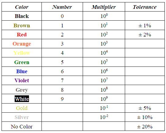
Notice that the colors on this resistor are (in order) Red, Green, Orange, and Silver.
1. The first line is the first digit → Red = 2
2. The second line is the second digit → Green = 5
3. The third line is the multiplier → Orange = 103
4. The last line (if any) is the tolerance → Silver = ± 10%
So the final answer would be 25 x 103Ω ± 10%
• Yes, I know it's not proper scientific notation this way. You can also write it as 25000 Ω
(notice there are three zeros), or even 2.5 x 10²Ω.
Resistors
There is always some resistance in every circuit.
• A circuit is always made up of some wire, so there will be some resistance there.
• Even the battery has parts that offer resistance to the flow of
electrons.
• The only circuits that come near to zero resistance are
superconductors.
• This resistance that is from the parts of the circuit itself (especially
the battery) is called internal resistance.
• This internal resistance is usually drawn into a circuit
diagram (schematic) as shown in Figure 1.
• Notice the squiggly line just before the positive terminal of
the battery? That’s to show the internal resistance of the
circuit.
• That symbol, drawn any other place in the circuit, represents an actual resistor placed in the
circuit.
• A resistor is a device found in circuits that has a certain amount of resistance.
Why would you ever want to add resistance to a circuit by using a resistor?
• The most common reason is that we need to be able to adjust the current flowing through a
particular part of the circuit.
• If voltage is constant, then we can change the resistor to change the current.
I=V
R If “V” is constant and we change “R”, “I” will be different.

Subscribe to:
Posts (Atom)