Showing posts with label Analog Electronics. Show all posts

Diode equation


Reverse Bias


When the diode is reverse-biased, a very small drift current due to thermal excitation flows
across the junction. This current (reverse saturation current, I0) is given, according to the
Boltzmann equation, by the formula:


where K0 is a constant depending on the pn junction geometry and V0 is the built-in voltage
of the diode (see chapter “Semiconductor Materials: pn junction”).


Forward Bias

When the diode is forward-biased through a voltage V , a small drift current flows again
across the junction. In that case, however, there is an additional component, the diffusion
current Vd, given by the formula:

These two currents have opposite directions, the total current is therefore given by:


Introduction


A diode is a dispositive made of a semiconductor material, which has two terminals or electrodes

(di-ode), that act like an on-off switch. When the diode is “on”, it acts as a short circuit
and passes all current. When it is “off”, it behaves like an open circuit and passes no current.
The two terminals are different and are marked as plus and minus in figure 1. If the polarity
of the applied voltage matches that of the diode (forward bias), then the diode turns “on”.
When the applied voltage polarity is opposite (reverse bias), it turns “off”. Of course this is
the theoretical behaviour of an ideal diode, but it can be seen as a good approximation for a
real diode.

Resistor


                            Resistors

                            Actual Resistors

                            Methods of Making Resistors

Methods of Making Resistors


There are two main methods that are used to make resistors.
• The most common is to just have a bunch of wire wound up inside that little cylinder.

• Known as wire-wound resistors, they depend on the fact that a certain length of a
certain piece of wire will have a certain resistance.


• These resistors tend to be very reliable (with low tolerances), but cost more because of
the price of metals used in them and the machinery needed to carefully cut and wind the
wire.
• The other type of resistor is made of a piece of
carbon.
• Known as a composition resistor, they
depend on the size of the piece of carbon,
and the fact that carbon is a metalloid (has
some metal-like properties) that does
conduct electricity.
• Because they are made from cheap
carbon, composition resistors can cost
much less than similar wire-wound
resistors. The drawback is that the carbon
can be cracked while making them, or become cracked in use. They have higher
tolerances because of the uncertainty in cutting the carbon.
In some cases it is necessary to have a circuit with resistors that you can adjust.
• These resistors are known as potentiometers or variable resistors.
• Often they are just a modified version of a wire-wound resistor, although newer
versions use advanced electronics instead.
• You’ve used one if you’ve ever used a dimmer switch for lights in a room, or played with an
electric race car set.
• Most variable resistors are designed so that by turning a dial or sliding a switch, you change the
amount of conducting material the current has to go through.
• The more conducting material the current has to go through, the higher the resistance…
less material and the resistance is less.


Actual Resistors


The resistors that you would most likely see if you opened up a CD player,
VCR, or other electronic device would look like the ones in Figure 2.

• They basically look like little cylinders with colored lines painted on
them.

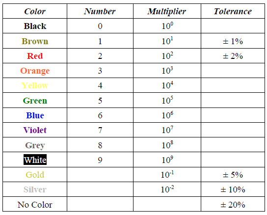
• The colored lines tell you the resistance and error range (tolerance) for

a resistor according to the following rules and table of numbers. You
do NOT have to memorize this table… it will be given to you if you
need it.
• To use the table you need to remember the following rules:
1. The first line is the first digit
2. The second line is the second digit
3. The third line is the multiplier
4. The last line (if any) is the tolerance
• Some resistors may have additional colored bands, but we will ignore them here.
• They usually have something to do with measuring things like failure rates or
temperature coefficients.

Example 1: What is the resistance of this resistor?


Notice that the colors on this resistor are (in order) Red, Green, Orange, and Silver.
1. The first line is the first digit → Red = 2
2. The second line is the second digit → Green = 5
3. The third line is the multiplier → Orange = 103
4. The last line (if any) is the tolerance → Silver = ± 10%
So the final answer would be 25 x 103Ω ± 10%
• Yes, I know it's not proper scientific notation this way. You can also write it as 25000 Ω
(notice there are three zeros), or even 2.5 x 10²Ω.


Resistors


There is always some resistance in every circuit.
• A circuit is always made up of some wire, so there will be some resistance there.
• Even the battery has parts that offer resistance to the flow of

electrons.
• The only circuits that come near to zero resistance are
superconductors.
• This resistance that is from the parts of the circuit itself (especially
the battery) is called internal resistance.
• This internal resistance is usually drawn into a circuit
diagram (schematic) as shown in Figure 1.
• Notice the squiggly line just before the positive terminal of
the battery? That’s to show the internal resistance of the
circuit.
• That symbol, drawn any other place in the circuit, represents an actual resistor placed in the
circuit.
• A resistor is a device found in circuits that has a certain amount of resistance.
Why would you ever want to add resistance to a circuit by using a resistor?
• The most common reason is that we need to be able to adjust the current flowing through a
particular part of the circuit.
• If voltage is constant, then we can change the resistor to change the current.
I=V
R If “V” is constant and we change “R”, “I” will be different.


simple music bell


This is the simplest ever musical calling bell that can be easily built. It uses the
musical 3 pin IC UM66 and a popularly known Transistor BC548b. The circuit

FM Transmitter

This circuit is a simple two transistor (2N2222) FM transmitter. No license is required for this transmitter according to FCC regulations regarding wireless microphones. If powered by a 9 volt battery and used with an antenna no longer than 12 inches, the transmitter will be within the FCC limits. The microphone is amplified by Q1. Q2, C5, and L1 form an oscillator that operates in the 80 to 130 MHz range. The

INDUCTOR


THE INDUCTOR

In its most basic form, an Inductor is simply a coil of wire. For most coils the current, (i) flowing through the coil produces a magnetic flux, (NΦ) that is proportional to it. According to Electromagnetism, when electrons flow through a conductor a magnetic flux is developed around the conductor producing a relationship between the direction of this flux and the direction of the electron flow called the "Left Hand Rule". But another important property of a wound coil is to use this magnetic flux to oppose or resist any changes in electrical current flowing through it.
The Inductor is another passive type electrical component designed to take advantage of this relationship by

CAPACITOR


The Capacitor or sometimes referred to as a Condenser is a passive device, one which stores energy in the form of an electrostatic field which produces a potential (Static Voltage) across its plates.
In its basic form a capacitor consists of two parallel conductive plates that are not connected but are electrically separated either by air or by an insulating material called the Dielectric.
When a voltage is applied to these plates, a current flows charging up the plates with electrons giving